FM Converters
The big problem with restoring Pre WWII FM radios is because they tune a completely different frequency range
compared with the current FM band. The FM band originally was set at 42-50 MHZ wheras today its at 88-108 MHZ.
One idea is to modify the old radios to be able to tune the new band, however this ruins the originality, and I do
not reccomend such an approach!
So, the next best way to receive FM broadcast on these radios is to use a converter. This in NO WAY damages or modifies
the radio, so it keeps its original design. There were a number of commercial converters built and sold after the war.
Some of them worked well, others did not. One of the best ones was made by E.H. Scott and used 3 Western Electric WE717
tubes.
Most of these converters have a switch to select the range of tuning. The need for this is because the old FM band was only 8 MHZ
wide and the new one is 20 MHZ wide. This problem is solved by having 3 ranges selected on the converter as shown in the pic below.
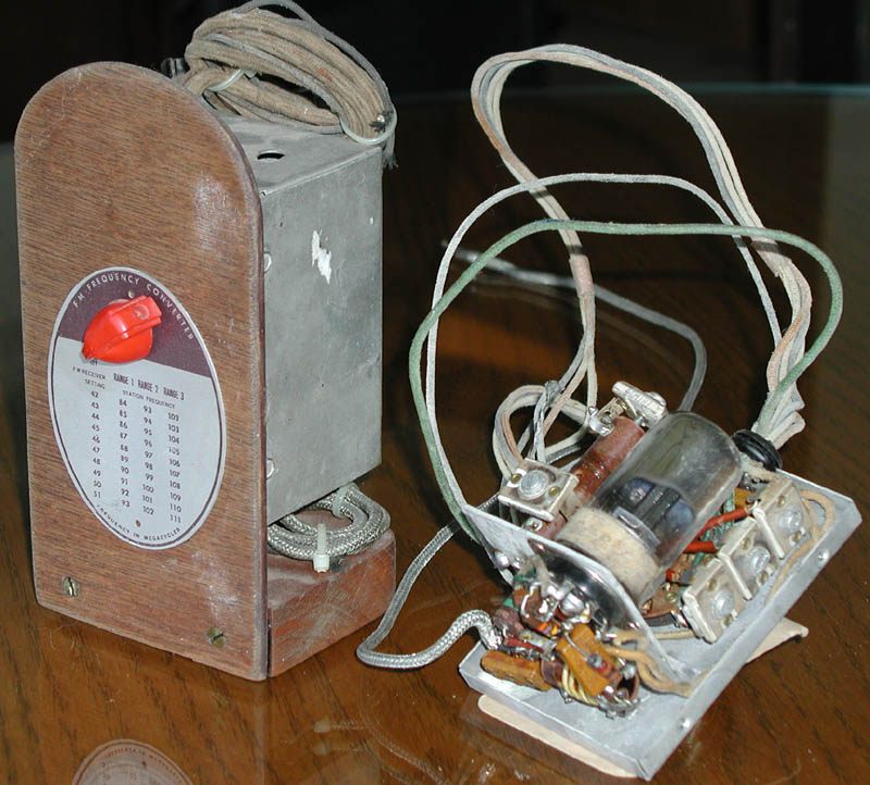
This converter was a commercially available one made after the war. I'm not 100% sure what company made
these but it might have been Hallicrafters as they are almost identical to their model CN-1. they both use a 7N7 Loctal tube.
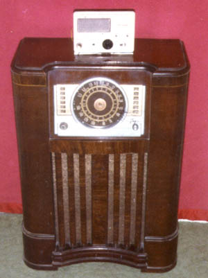
One of the first antique radios I acquired was a 1942 Crosley model 22CA. This radio has the Pre-War FM band and I wanted to
be able to receive FM stations on it. In 1983, while I was in the 10th grade, a friend helped me design and build an FM
converter on an old defunct Heathkit Twoer chassis (don't worry, this "Benton Harbor Lunchbox" was beyond saving). The converter
worked well enough, but over time it drifted and the radio had to be retuned as it was in operation. It also had a tuned
front end RF amplifier which required tuning as you dialed in your station. Unfortunatly, this converter no longer exists
and the only evidence I have of its existence is in the picture of the Crosley 22CA shown above. As I recall, it used 3 tubes.
a 6BK7 cascode RF amplifier, 6U8 Mixer/Oscillator and a 6CB6 IF amplifier.
I was not satisfied with this arrangement, so many years later, I tried another attempt to make an FM converter. By this time
I had more Pre-War FM radios in my collection and the converter I had just wasn't good enough (in my opinion).
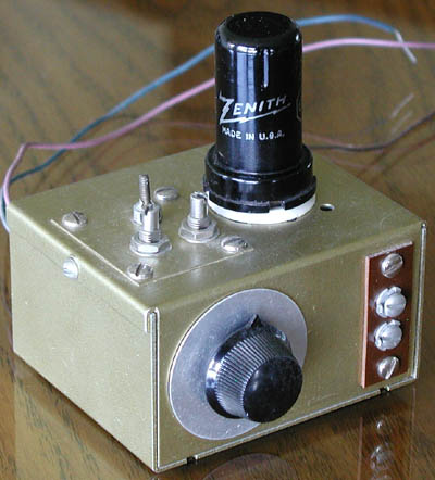
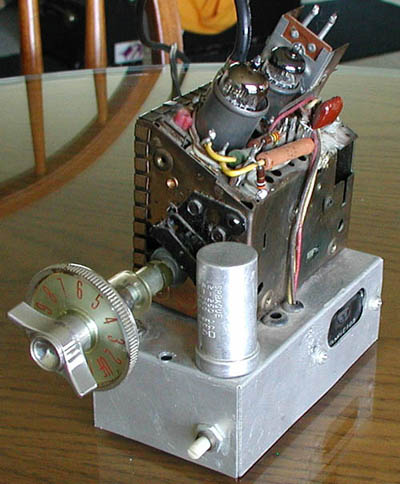
This little golden gem was the result. It worked, but drifted as well and was not as sensitive as the "Twoer" converter.
(as I remember, it was worse at drifting)
It used a 6SB7Y Pentagrid Converter tube which was common in post-war FM radios.
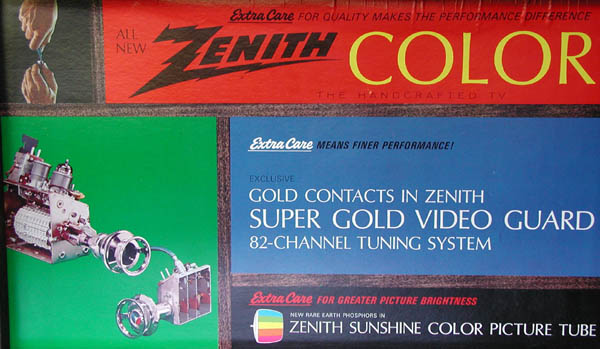
I wanted a better converter. One that was stable, sensitive, easy to adjust and reliable. Along about 1991, an idea hit me.
"Why not use an old Television tuner!?!?!" Older mechanical TV tuners lend themselves quite well to the
task! They receive frequencies below and above the current FM broadcast band AND they are designed to output into a 40 MHZ
IF amplifier! Since I worked at a TV repair shop, I had MANY old tuners to choose from. The choice was actually obvious,
Zenith's Gold Video Guard tuner.
This tuner has all the different channels in "Strips" which are installed in a "turret" which is rotated
as you turned the channel selector knob of the TV. As the strips are selected, a row of contacts make connection to the strips
to tune that channel. Another bonus, each strip has its own individual oscillator tuning screw which is engaged by the Fine Tuning
knob which is an outer ring around the channel selector knob!
PERFECT!
I only need 3 of the 13 strips in the tuner, so most of them were left out. I used a Grid-Dip meter to retune the 40 MHZ output
coil to 46 MHZ which it easily reached by only tuning the slug. I modified the strips for channels 4, 5, and 6 to tune the FM
band. First I made a make-shift coil for my Grid-Dip meter to reach the strips when they were in contact with the tuner, then
carefully removed turns, one at a time untill each coil was within the FM broadcast band.
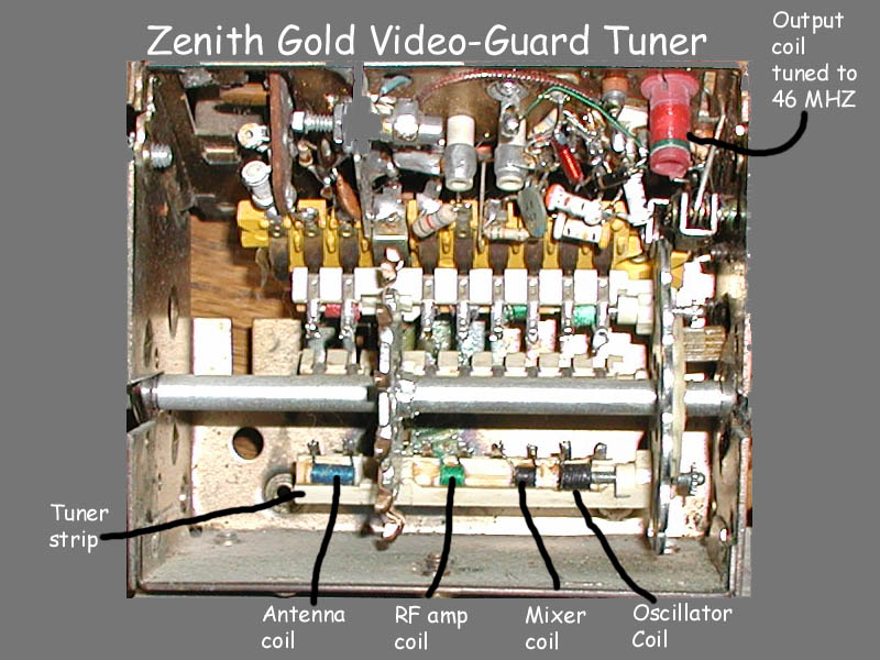
On the first strip, the antenna coil is tuned to around 89 MHZ, the RF coil is tuned to around 92 MHZ and the mixer coil is tuned
to around 95 MHZ to give the tuner a broad even response. The oscillator coil was tuned using a frequecy counter untill it was
at 138 MHZ when the fine tuning slug was midway in its travel.
The second strip was tuned similarly except to tune the next part of the band. Antenna=97 MHZ, RF=100 MHZ, Mixer=104 and the
oscillator set to 147 MHZ.
I mounted the modified tuner to a small chassis and built a power supply to power it as well as a small bias supply to control
the RF gain (connected to the tuner's AGC line) This tuner also had an AFC (Automatic Frequency Control) line which had to be
biased at the right voltage. Fortunatly, the Zenith service literature showed how to do this so you could put a tuner with AFC
into a television that did not have this capability.
The result was a VERY stable, sensitive, easily adjusted reliable FM converter! It works great on any of my pre-war FM radios!
Zenith later made the same tuner in a solid state form and I also modified one and it works just as well, however since the
radios use tubes, I like the idea that the converter uses tubes as well. Which BTW, these tuners used a 6HA5 RF amplifier tube
and a 6GJ7 Mixer/Oscillator tube.
I will upload a complete schematic of this project and hopefully more instruction of how to modify a tuner to be a converter
sometime in the near future.
more information about FM converters can be found on this website
More to come