The following is from Chapter 7 of "The Radio Handbook, 16th Edition". Editor William I. Orr, W6SAI. Published by Editors and Engineers, LTD ©1962.
7-4 Amplifier Construction
Wiring Techniques
Assembly and layout of high fidelity audio amplifiers follows the general technique described for other forms of electronic equipment. Extra care, however, must be taken to insure that the hum level of the amplifier is extremely low. A good hi-fi system has excellent response in the 60 Hz region, and even a minute quantity of induced A-C voltage will be disagreeably audible in the loudspeaker. Spurious eddy currents produced in the chassis by the power transformer are usually responsible for input stage hum.
: To insure the lowest hum level, the power transformer should be of the "upright" type instead of the "half-shell" type which can couple minute voltages from the windings to a steel chassis. In addition, part of the windings of the half-shell type project below the chassis where they are exposed to the input wiring of the amplifier. The core of the power transformer should be placed at right angles to the core of a nearby audio transformer to reduce spurious coupling between the two units to a minimum.
: It is common practice in amplifier design to employ a ground bus return system for all audio tubes. All grounds are returned to a single heavy bus wire, which in turn is grounded at one point to the metal chassis. This ground point is usually at the input jack of the amplifier. When this system is used, A-C chassis currents are not coupled into the amplifying stages. This type of construction is illustrated in the amplifiers described in this chapter.
: Care should be taken to reduce the capacitance to the chassis of high impedance circuits, or the high frequency response of the unit will suffer. Shielded "bath-tub" type capacitors should not be used for interstage coupling capacitors. Tubular paper capacitors are satisfactory. These should be spaced well away from the chassis.
: It is a poor idea to employ the chassis as a common filament return, especially for low level audio stages. The filament center-tap of the power transformer should be grounded, and twisted filament wires run to each tube socket. High impedance audio components and wiring should be kept clear of the filament lines, which may even be shielded in the vicinity of the input stage. In some instances, the filament center tap may be taken from the arm of a low resistance, wirewound potentiometer placed across the filament pins of the input tube socket. The arm of thos potentiometer is grounded, and the setting of the control is adjusted for minimum speaker hum
7-5 the "Baby Hi Fi"
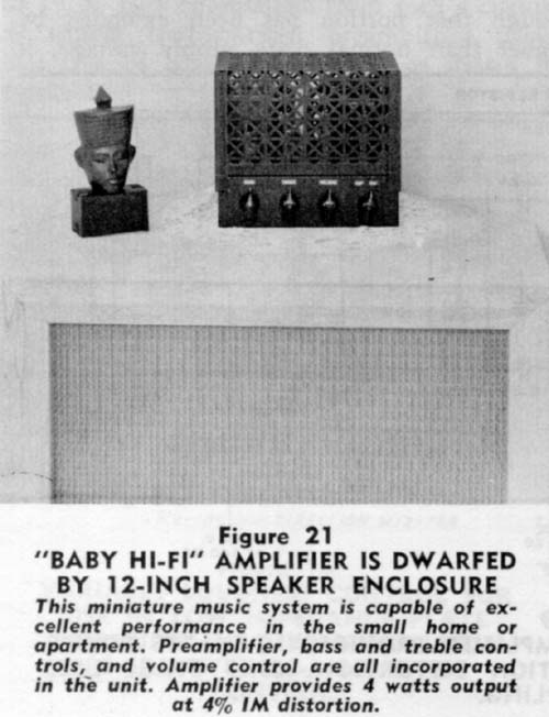 A definite need exists for a compact, high fidelity audio amplifier suitable for use in the small home or apartment. Listening tests have shown that an average power level of less than one watt in a high efficiency speaker will provide a comfortable listening level for a small room, and levels in excess of two or three watts are uncomfortably loud to the ear. The "baby Hi-Fi" amplifier has been designed for use in the small home, and will provide excellent quality at a level high enough to rattle thye windows.
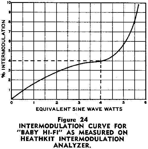
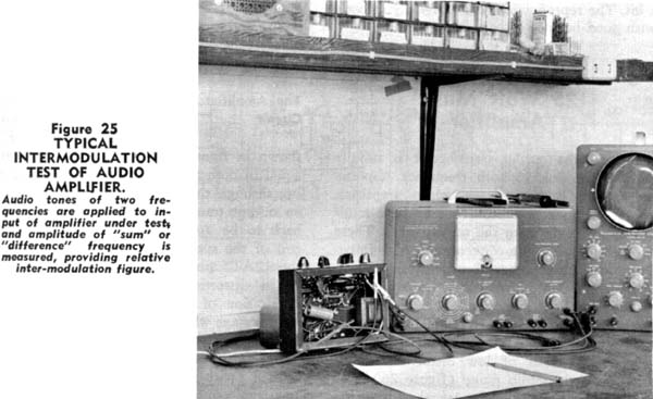
: Designed around the new Electro-Voice miniature ceramic cartridge, the amplifier will provide over 4 watts power, measured at the secondary of the output transformer. At this level, the distortion figure is below 1%, and the IM figure is 4%. At normal listening levels, the IM is much lower, as shown in figure 24.
The Amplifier Circuit
: The schematic of the amplifier is shown in figure 22. Bass and treble boost controls are incorporated in the circuit, as is the volume control. A dual purpose 12AU7 double triode serves as a voltage amplifier with cathode degeneration. A simple voltage divider network is used in the grid circuit to prevent amplifier overloading when the ceramic cartridge is used. The required input signal for maximum output is of the order of 0.3 volts. The output level of the Electro-Voice cartridge is approximately twice this, as shown in figure 7. The use of this high-level cartridge eliminates the necessity of high gain amplifiers required when low level magnetic pickup heads are used. Problems of hum and distortion introduced by these extra stages are thereby eliminated, greatly simplifying the amplifier. The second section of the 12AU7 is used for bass and treble boost. Simple R-C networks are placed in nthe grid circuit permitting gain boost of over 12 db at the extremities of the response range of the amplifier.
: A second 12AU7 is employed as a direct coupled "hot-cathode" phase inverter, capacity coupled to two 6AQ5 pentode connected output tubes. The feedback loop is run from the secondary of the output transformer to the cathode of the input section of the phase inverter.
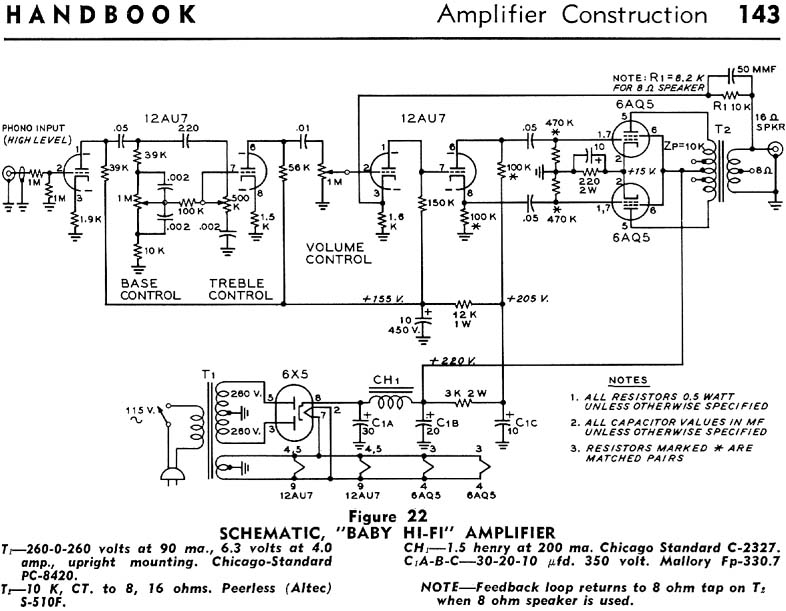
: The power supply of the "Baby Hi-Fi" consists of a 6X5-GT rectifier and a capacitor input filter. A second R-C filter sectionis used to smooth the d-c voltage applied to the 12AU7 tubes. A cathode-type rectifier is used in preference to the usual filament type to prevent voltage surges during the warm-up period of the other cathode-type tubes.
Amplifier Construction
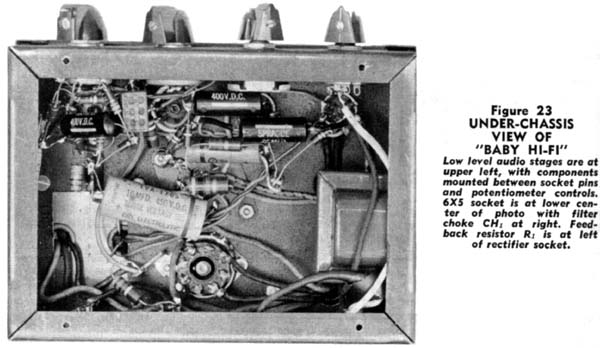
: The complete amplifier is built upon a small "amplifier foundation" chassis and cover measuring 5"x7"x6' (Bud CA-1754). Height of the power amplifier including dust cover is 6". The power transformer (T1) and output transforer (T2) are placed in the rear corners of the chassis, with the 6X5-GT rectifier socket placed between them. The small filter choke (CH1) is mounted to the wall of the chassis and may be seen in the under-chassis photograph of figure 23. The four audio tubes are placed in a row across the front of the chassis. Viewed from the front, the 12AU7 tubes are to the left, and the 6AQ5 tubes are to the right. The three section filter capacitor (C1A,B,C) is a chassis mounting unit, and is placed between the rectifier tube and four audio tubes. Since the chassis is painted, it is important that good grounding points be made at each tube socket. The paint is cleared away beneath the socket bolt heads, and lock nuts are used beneath the socket retaining nuts to insure a good ground connection. All ground leads of the first 12AU7 tube are returned to the socket, whereas all grounds for the rest of the circuit are returned to a ground lug of filter capacitor C1.
: Since the input level to the amplifier is of the order of one-half volt, the problem of chassis ground currents and hum is not so prevailent, as is the case with a high gain input stage.
: Phonograph-type coaxial receptacles are mounted on the rear apron of the chassis, serving as the input and output connections. The four panel controls (bass boost, treble boost, volume and a-c on) are spaced equidistant across the front of the chassis.
Amplifier Wiring
The filament wiring should be done first. The center-tap of the filament winding is grounded to a lug of the 6X5-GT socket ring, and the 6.3 volt leads from the transformer are attached to pins2 and 7 of the same socket. A twisted pair of wires run from the rectifier socket to the right-hand 6AQ5 socket (figure 23). The filament leads then proceed to the next 6AQ5 socket and then to the two 12AU7 sockets in turn.
: The 12AU7 preamplifier stage is wired next. A two terminal phenolic tie-point strip is mounted to the rear of the chassis, holding the 12K decoupling resistor and the positive lead of the 10 µfd 450-volt filter capacitor. All B-plus leads are run to this point. Most of the components of the bass and treble boost system may be mounted between the tube socket terminals and the terminals of the two potentiometers. The feedback resistor R1 is mounted between the terminal of the coaxial output connector and a phenolic tie-point strip placed beneath an adjacent socket bolt.
: When the wiring has been completed and checked, the amplifier should be turned on, and the various voltages compared with the values given on the schematic. It is important that the polarity of the feedback loop is correct. The easiest way to reverse the feedback polarity is to cross-connect the two plate leads of the 6AQ5 tubes. If the feedback polarization is incorrect, the amplifier will oscillate at a super-sonic frequency and the reproduced signal will sound fuzzy to the ear. The correct connection may be determined with the aid of an oscilloscope, as the oscillation will be easily found. The builder might experiment with different values of feedback resistor R1, especially if a speaker of a different impedance is employed. Increasing the value of R1 will decrease the degree of feedback. For an 8-ohm speaker, R1 should be decreased in value to maintain the same amount of feedback.
: This amplifier was used in conjunction with a General Electric S-1201A 12-inch speaker mounted in an Electro-Voice KD6 Aristocratspeaker enclosure which was constructed from a kit. The reproduction was extremely smooth, with good balance of bass and treble.
7-6 A Transformerless 25 Watt Music Amplifier
: Because the output transformer is usually the weakest link in both frequency response and power output of an audio amplifier, several methods have been used to drive loudspeakers directly from the output tubes. these have either used non-conventional high-impedance loudspeakers, have been very inefficient, or have had low power output capabilities.
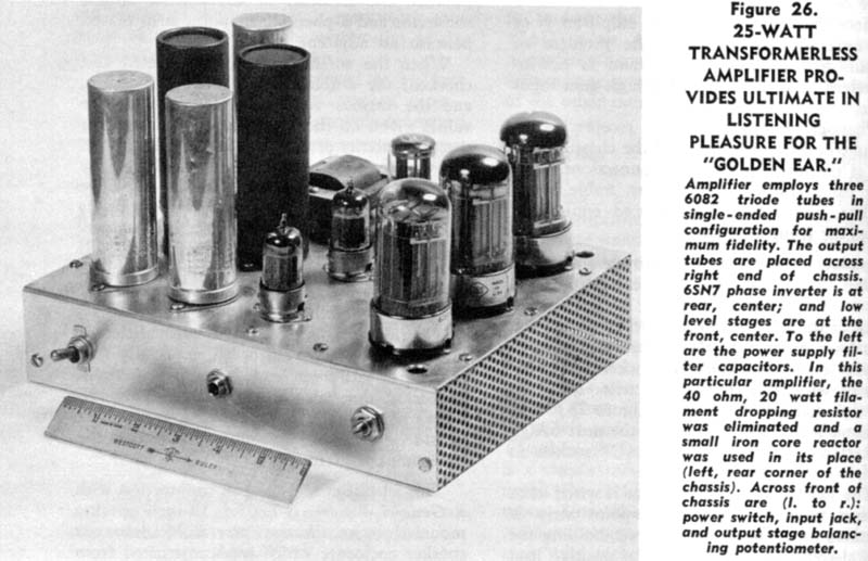
: The amplifier described in this section drives a conventional 16 ohm loudspeaker with normal class A amplifier efficiency, and supplies 25 watts of low disortion output throughout the audio range (figure 26). The amplifier requires an input signal of approximately one volt to drive it to maximum output. The unit attains its high performance through the use of 40 db of inverse feedback. Because of the relatively simple power supply requirements and the absence of expensive power and audio transformers it is more economical than conventional amplifiers of similar performance.
The Amplifier Circuit
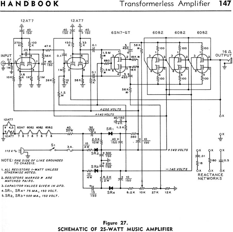
: The output stage of this unusual amplifier is the single ended, push-pull type as shown in figure 27. The quiescent current is equal in both tubes with no d.c. current flowing through the speaker load. The absence of an output transformer allows 40 db of feedback to be applied by connecting the voice coil of the speaker directly to the cathode of the 12AT7 phase-inverter driver. In addition to its distortion reducing characteristic, the application of feedback serves to reduce the hum voltage which might otherwise be present. As the gain within the feedback loop is essentially unity, an additional voltage amplifier is used (with seperate feedback) to build the input voltage up to the voice coil level.
: The power supply is a double half-wave selenium rectifier circuit developing +140 and -140 volts with respect to ground. The supply uses large filter capacitors, and no extra filtering is required. The output impedance of the supply is extremely low. To obtain higher voltage for the low level stages, additional selenium rectifiers are used in a voltage-adding configuration to obtain +250 and -250 volts.
Circuit Details
: The complete schematic of this amplifier is given in figure 27. Three type 6082 double triodes are employed in the output stage. These are 26.5 volt versions of the popular 6AS7G. These tubes are capable of 700 milliamperes of peak plate current per triode section at the plate voltage employed. The choice of the 6082 is an economy measure to allow the use of a series heater string. These tubes cut off at about -70 volts, but for this class of service the bias is held at -60 volts. A bias conrol is provided for one set of tubes so that the d.c. current flowing in the tubes may be equalized, and to insure that no d.c. current flows through the speaker voice coil.
: The type 6082 tube is not rated for use with fixed bias unless a limiting resistor is added in either the plate or the cathode circuit. Although this circuit does not use such resistors, their omission is feasible only because the tubes are used under quiescent conditions well below maximum ratings. With tubes of this type, it may be expected that the average current through the voice coil will drift with time but the presence of this unbalance current will generally be of little concern. In any event, the circuit has been designed so that the output stage can be conveniently rebalanced.
The Voltage Amplifier
: The low level stages are all operated Class A with conventional circuitry. A separate driver is needed for each side of the output circuit, as insufficient output is obtained from the phase inverter to drive the output tubes directly. One side of the phase inverter has a larger load than the other, since the input to the lower group of output tubes has the speaker impedance in the cathode. This causes degeneration and necessitates higher input voltage than the upper group.
: In the first voltage amplifier, bias is obtained from the unbypassed cathode resistors since the loss of gain can easily be tolerated. The phase inverter-driver, however, has fixed bias applied to the grid from the -140 volt supply, since maximum gain is desired within the main feedback loop.
The Power supply
: The high current power supply uses 300 µfd. filter capacitors and 5 ohm protective resistors. R-C decoupling is used to minimize hum in the low level audio stages. As with all "power-transformerless" equipment, care must be taken when connecting this amplifier to other pieces of equipment to ensure that the grounded side of the power line is connected to the chassis. This may be achieved by the use of a polarized line plug, or a small isolation transformer may be employed.
The Equlalizing Circuit
: As would be expected, 40 db of feedback can only be applied within a loop having a minimum of phase shift or circuit instability will result. Since the loudspeaker impedance becomes inductive above the audio range it causes an increase in phase shift and loop gain. To avoid instability an impedance can be shunted across the voice coil to prevent the output reactance from rising at the higher audio frequencies. Three networks that have been used succcessfully for this purpose are shown in figure 27. The 180 ohm resistor merely limits the maximum impedance of the output system and thus prevents excessive feedback. The 0.5 µfd. capacitor places a low impedance across the inductive load which is effective at the higher audio frequencies. The series 16 ohm resistor and 0.01 µfd. capacitor places a resistance across the speaker at the higher frequencies and an open circuit at the lower frequencies. This serves to provide constant impedance and feedback over the frequency range of the amplifier.
: The balance adjustment for zero d.c. current through the speaker voice coil can be made with a milliammeter in series with the coil, or by measuring the voltage across the coil with a sensitive voltmeter.
Amplifier Construction
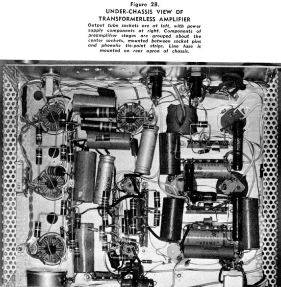
: The amplifier is built upon an aluminum chassis measuring 8" x 10" x 2". perforated end pieces and 1/4-inch holes drilled around the 6082 tube sockets insure adequate ventilation. Layout of the major components is shown in figure 26, and placement of the under-chassis components is shown in figure 28. As no a.c. power transformer is used, ground currents are of small concern, and the ground bus wiring technique need not be employed. In its place, a tinned copper wire is run between the various chassis ground points. ground connections may now be made to the socket grounding lugs, or to terminal strip ground points. A.c. filament and power leads are twisted whenever possible, and are run around the outer edges of the chassis.
: Point-to-point wiring technique is used, with small capacitors and resistors mounted to socket pins or to phenolic tie-point strips placed near the sockets. The small silicon rectifiers are mounted to tie-point strips placed near the upright filter capacitors.
: Several of the filter capacitors do not have their negative terminal at ground potential. It is therefore necessary to mount the capacitor on a phenolic plate and to slip a fiber insulating jacket over the metal shell.
Amplifier Performance
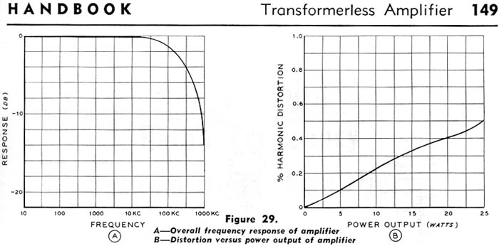
: The frequency response of the amplifier is flat within one db from 10 Hz to over 100 KHz. since R-C coupled circuits are used throughout, there is no serious limitation on frequency response, and the response is down only 4 db at 250 KHz, The interstage coupling networks limit the low frequency response below 10 Hz.
: Harmonic distortion and intermodulation at full rated output are exceptionally low and virtually independent of frequency. The ability to deliver 25 watts at 20 Hz and below with negligible distortion is practically impossible in a transformer-type circuit of similar mid-frequency power rating. Square wave response of the amplifier as measured between 20 Hz and 50 KHz is extremely good.